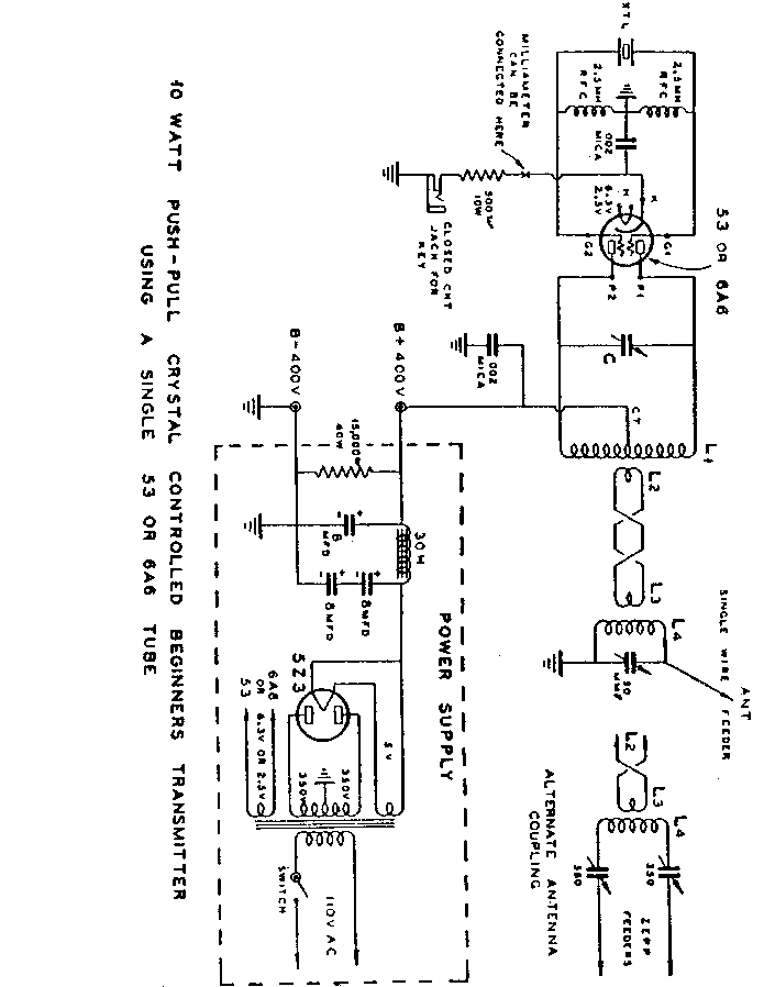
The original Frank Jones 10 watt, push-pull, crystal controlled, "beginners transmitter" from his book, "The Radio Amateur Newcomer", first printed in 1935 or so.
Click on the above link to view and/or print the schematic.
Note the extreme simplicity and paucity of parts. The tube shown, a type #53 (2.5 volt filament) or the 6A6 (6.3 volt filament), is functionally equivalent to our more modern 6N7, although probably ANY small twin-triode would work fine. The 6BL7 will provide about 25 watts input. The 6SN7 will provide about 10 watts input, and the 6SL7 will provide about 3 watts input. I intend to use this circuit for my experimental 12AX7 15 watter.
This little circuit was recently described by Dr. Arnaldo Coro, CO2KK, of Havana, Cuba, as "the magic circuit". He is using it with any of either 6J6, 12AX7, a pair of 6AG7s, etc., and tells us that he has made it operate from 1.5 mHz through 48 mHz. It keys beautifully and is very easy to build. Arnie uses home made RF chokes.
I have also used this circuit with an 829B/3E29 tube to build a 20 Mhz. RF source for one of our professors' research project. The power output with the power supply available is 12 watts. Signal is very good. I used one of those tiny computer crystals.
For 80 meters, L1 is 51 turns of #22 DSC or DCC (Double Silk Covered or Double Cotton Covered) wire, close wound, on a 1 1/2" diameter form, with the center-tap (CT) at turn #26. For 40 meters, L1 is 25 turns of #16 enameled wire, space-wound, on a 1 1/2" diameter form, with the CT at turn #13. C is a 50 pfd wide-spaced tuning capacitor. Since neither DCC or DSC wire are easily available any more, use vinyl-covered solid hook-up wire instead. 1 1/4" PVC plumbing pipe is a little over 1 1/2" outside diameter, and will work quite well in this rig. L2 is a one or two turn link wound over the CENTER (the "cold-end") of L1. I would use a very short piece of PVC large enough to fit over L1 as the coil form for L2 and L3, and cement it in place. I would make my links out of #16 solid wire. L2 and L3 are connected together by a "twisted-pair". Twisted zip-cord, with 4 to 8 twists per foot, would work quite well here. L4 is a coil of the same dimensions as L1, but without the CT. L3 must go over the "cold-end" of L4. If you are using an end-fed wire antenna, the cold-end of L4 will be the grounded end. For the Zepp, the "cold-end" is the center of the coil.
I will post a photo of my 829B rig asap.